Exposure index (EI)
About[]
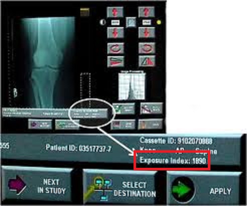
Exposure index (EI) is the measure of the amount of exposure received by the image receptor (IR). It is dependent on mAs, total detector area irradiated, and beam attenuation. The exposure index is indicative of the image quality. EI is derived from the mean detector entrance exposure which is in turn derived from the mean pixel value of the image. Although EI is always derived from the IR exposure, equipment manufacturers calculate the numeric value differently, resulting in different ranges and definitions. [1]By verifying EI values, technicians can use these values to verify Automatic Exposure Control (AEC) dose set points with CR/DR modalities.
Know distances[]
The formula for cm to in SID conversion is that 1 cm is 0.4 inches. Therefore, to convert 100 cm to in take 100 centimeters multiplied by 0.3937008 which equals 70 inches.
Most common SIDs[]
These are the common SID distances:
- 100 cm equals 40 inch
- 180 cm equals 70 inch
Most common cassette sizes[]
These are the common cassette distances:
- 20 cm x 30 cm equals 8" x 12"
- 43 cm x 76 cm equals 17" x 14"
OEM Values[]
Although EI is always derived from the IR exposure, equipment manufacturers calculate the numeric value differently, resulting in different ranges and definitions (Carlton & Adler, 2006, p. 367; Neitzel, 2004, p. S231). Also, there is variation between units purchased from the same manufacturer based on different IRs and software (Carlton & Adler, 2006, p. 367). Different IRs have different detective quantum efficiency (DQE). A high DQE results in lower noise levels (AAPM, 2009, p. 3). Therefore, all systems have a different index and are difficult to compare across systems.
Fuji CR[]
Fuji uses a sensitivity number (S) that is related to the amount of amplification required by the photomultiplier tube to adjust the digital image. S is inversely proportional to exposure. Properly exposed images should have an S between 150-250 (Carlton & Adler, 2006, p. 367).
The Fuji CR formula is:

Carestream (Kodak) CR[]

Normal Carestream EI values for 0.5mmCu+1mmAL=400 +/-5%

QA meter placement for AEC cells and EI testing of
Carestream (Formerly Kodak) uses the term Exposure Index (EI), which is directly proportional to exposure. Some Kodak CR processors properly exposed images should have an EI between 1,800-2,200 (Carlton & Adler, 2006, p. 367). A Carestream CR-85X processor exposed images should have an EI between 300-600. A change of 300 in the EI indicates a change of a factor of 2 in the exposure to the IR. The EI is calibrated so that a 1 mR exposure from 80 kVp at 125mA beam filtered by 1.5 mm AL and .5 mm Cu (copper) which simulates a chest exposure will yield a value of 2000 EI. A QA meter is inserted under the AL + Cu filters to obtain mR readings. After that, the CR cassette is processed following a 15-minute delay after x-ray exposure. A mR value is recorded from a QA meter.
The Carestream (Kodak)formula:

An exposure of .1 mR results in an EI of 1000, 1 mR results in an EI of 2000, and an exposure of 10 mR results in 3000.For every double (x2) in mAs, the EI should increase about 300. Every time you 1/2 your mAs, it should reduce the EI by 300.[3]
Agfa LgM[]
Agfa CRs uses log median exposure (LgM) or Exposure Index (EI). This system compares the exposure level of the image to a baseline established for the department. LgM is mapped to a 12-bit pixel called the Scan Average Level (SAL). Since it is based on a log system, an increase of 0.3 means the dose was doubled (Carlton & Adler, 2006, p. 367). An optimal exposure lies between 1.9 and 2.5.
The Agfa LgM formula is:
![{\displaystyle SAL=[1800x(SC/200)x(uGy/20)]}](https://services.fandom.com/mathoid-facade/v1/media/math/render/svg/1b7f95040510360f1e2817702c505e6e0bd295de)
Procedure[]
1. Based on “Flat Field” test
2. 40" SID, 75 kVp, 13"x13" field size
3. 1.5 mm Cu filter, 20 cm thckness, no grid
4. Adjust to 10 uGy at receptor (~1.1 mR)
5. Expose cassette transversely, full coverage
6. Rotate cassette 180 degrees and expose again
7. Calibrate reader to get SAL=1800 +/-100
Relative exposure for same LgM if Agfa CR scan level calibrated using protocols of other manufacturers. SAL measured via normal Agfa procedure (two 1-mR exposures with plate rotated 180 degrees) Delay time equals 5 minutes before exposure.
Agfa EI[]
Agfa CRs uses Exposure Index (EI) or log median exposure (LgM). This system compares the exposure level of the image to a baseline established for the department.
Procedure[]
1. Based on “Flat Field” test
2. 40" SID, 75 kVp, 13"x13" field size
3. 1.5 mm Cu filter, 20 cm thckness, no grid
4. Adjust to 10 uGy at receptor (~1.1 mR)
5. Expose cassette transversely, full coverage
6. Rotate cassette 180 degrees and expose again
7. Calibrate reader as needed (see EI table)
Template:EITable
EI is measured via normal Agfa procedure (two 1-mR exposures with plate rotated 180 degrees). Delay time equals 5 minutes before exposure.
Philips DR[]
Philips uses an EI that is inversely proportional to exposure. This index is represented in bigger discrete steps (eg., 100, 125, 160, 200, 250, 320, 400, 500, etc). Each step requires a 25% change in exposure to occur (AAPM, 2009). An optimal exposure lies between 200 and 800.
Imaging Dynamics DR[]
Imaging Dynamics uses f#. The f# compares the exposure to an established target exposure. Negative values represent underexposure, while positive values indicate overexposure (AAPM, 2009).
Canon DR[]
Canon uses a reached exposure value (REX). REX is a function of the brightness and contrast as selected by the operator (AAPM, 2009).
GE DR[]
GE uses the detector exposure index (DEI) which compares the detector exposure to the expected exposure value (AAPM, 2009).
Siemens[]
Siemens uses an Exposure Index (EXI). EXI is calculated by dividing the field into a 3x3 matrix and assessing only the central segment, and is based on the selected organ program. EXI is directly proportional to dose. Doubling dose doubles the EXI. EXI depends on organ program, whether manual exposure or AEC was used, and the measuring field (AAPM, 2009).
Future Developments[]
In 2008, the International Electrotechnical Commission (IEC) developed and published the International Standard IEC 62494-1 on the definition and scaling of the exposure index for digital radiography. According to the standard the EI shall be proportional to the exposure (air kerma) and shall be scaled as EI = 100 * X, where X is the air kerma at the detector, at the calibration beam quality. It is expected that this standard definition will be implemented in future digital radiography systems.
The American Association of Physicists in Medicine (2009), published a document in July, 2009 with the purpose of identifying a standard index which reflects the adequacy of the exposure received by the IR.[4][5][6][7][8]
Reference[]
- ↑ Conference of Radiation Control Program Directors, Inc. "COMPUTED RADIOGRAPHY (CR) AND DIGITAL RADIOGRAPHY (DR) STATE X-RAY INSPECTION PROTOCOL--Publication No. E-10-2 " Jan 2010. http://www.crcpd.org/pubs/CR&DR_Protocol.pdf
- ↑ acqueline Gallet. Kodak. "The Concept of Exposure Index For CARESTREAMDIRECTVIEWSystems." www.carestream.com/cr-exposure-whitePaper-M1-461.pdf
- ↑ Eliot L. Siegel, Robert M. Kolodner. Filmless Radiology. p 149. 2006.
- ↑ American Association of Physicists in Medicine. (2009). An Exposure Indicator for Digital Radiography. Retrieved from http://www.aapm.org/pubs/reports/rpt_116.pdf
- ↑ Bontrager, K. L., & Lampignano, J. P. (2005). Textbook of radiographic positioning and related anatomy (6th ed.). Elsevier Science.
- ↑ Carlton, R. R. & Adler, A. M. (2005). Principles of radiographic imaging: An art and a science. Delmar Learning.
- ↑ International Electrotechnical Commission (2008). IEC 62494-1 ed. 1 Medical electrical equipment - Exposure index of digital x-ray imaging systems - Part 1: Definitions and requirements for general radiography
- ↑ Neitzel, U. (2004). Management of pediatric radiation dose using Philips digital radiography. Pediatric Radiology, 34(Suppl 3), S227-S233.