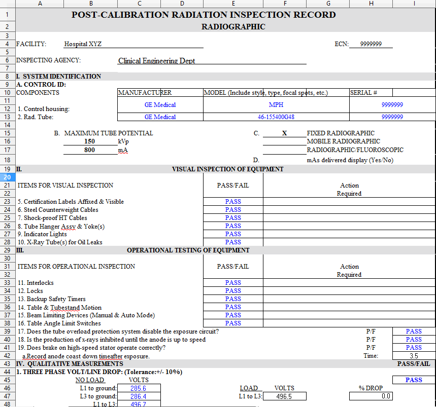
Post Calibration Radiation Inspection (PCRI) Radiographic Sample Form
About
The Post Calibration Radiation Inspection (PCRI) is an inspection record for conventional radiography that details the step-by-step inspections and examinations prepared by trained agencies on the serviceability, quality assurance and control, as well as the functionality and operation of these ionizing radiation devices onto a document that complies with mandatory Federal, State, and Local Laws, Regulations & Performance Standards. The following PCRI is a mandatory requirement to be performed after new installations and repairs as well as during routine annual calibrations and safety inspections. The frequency for each test below are not final and technicians should always follow the most stringent standards and local policies.
System Identification
The system identification or equipment identification is the medical devices and its system components including the master control, room control, radiographic tube head's make and model, manufacturer name, and the device serial number used for FDA tracking and QA documentation. Additionally, we will input the systems highest kVp and mA that can be selected on dial and displayed on the the master control.
Visual inspection
Visual Inspection, used in maintenance of medical equipment, means inspection of equipment and structures using all of the human senses such as vision, hearing, touch and smell and/or any non-specialized inspection equipment to include tape measures and/or magnetic angle measuring tool to verify proper operation.
Test Frequency
Annually
Test Tools
A tape measure and magnetic angle measuring tool.
Procedures
The following are some common verification inspections for general radiologic devices:
Pass or fail
- CERTIFICATION LABELS ARE AFFIXED AND VISIBLE
- STEEL COUNTERWEIGHT CABLES
(Ensure cables are clean and free from dust and other debris)
- SHOCK-PROOF HIGH TENSION CABLES
- TUBE HANGER ASSEMBLY AND YOKES
- INDICATOR LIGHTS
- X-RAY TUBES FOR OIL LEAKS
- INTERLOCKS
(Door and table interlocks shall forbid exposure when in the open position. This includes the fluoroscopic primary barrier, which shall be in position for use in order for fluoroscopic exposure to be possible.)
- LOCKS and EXPOSURE SWITCHES
(At exposure times of 0.5 sec or more the switch must terminate the exposure if manual pressure is removed.)
- VIEW BOXES
(The brightness of the view boxes used to check films after processing shall be within 15% of the brightness of the view boxes used by the radiologists to read the films.)
- LEAD APRONS, GLOVES, AND DRAPES
(Protective garments and drapes shall not have tears, which impair their radiation protection function.)
- BACKUP SAFETY TIMERS
- TABLE AND TUBE STAND MOTION
- BEAM LIMITING DEVICES (Manual and automatic mode)
- TABLE ANGULATION LIMIT SWITCHES
(Record angle in degrees using a magnetic angle measuring tool)
- DOES TUBE OVERLOAD PROTECTION CIRCUIT DISABLE EXPOSURE CIRCUIT?
- IS THE PRODUCTION OF X-RAYS INHIBITED UNTIL ANODE IS UP TO SPEED?
- DOES BRAKE ON HIGH SPEED STATOR OPERATE CORRECTLY?
(Record coast down time for anode after exposure
Three/Single Phase Voltage/Line Drop
(WARNING: LETHAL VOLTAGES PRESENT)
The Three or Single Phase Voltage or Line Drop is a test to the power quality of the incoming power to the x-ray device and its components. If power coming into the machine has dirty electicity then there can be no proper alignments to adjustments madeto the actual x-ray machine until that power has been cleaned up.
Test Frequency
Annually
Test Tools
A Digital Multimeter with VAC mode
Procedures
No Load
A Digital Multimeter (DMM) will be used to measure the incoming power (in VAC)from the circuit breaker panel. This is called the no load test. You will measure multiple test spots marked "L1" (red lead) to the metal case (black lead goes to Ground). Next, you will proceed to measure "L3" (red lead) to ground (black lead) and finally L1 (red lead) to L3 (black lead). Record all of the following measurements taken.
Load
A Digital Multimeter (DMM) will be used to measure the incoming power (in VAC) from the circuit breaker panel while an x-ray is being taken at 90 kvP and 250 mA. This is called the load test. You will measure a single test spot marked "L1" (red lead) to "L3" (black lead) under an x-ray shot. The voltage drop will be quick so watch carefully. Record the following measurement taken. Finally, the percentage drop should be less than 10%.
Exposure / Timer Accuracy
The Exposure / Timer directly affects the total quantity of radiation emitted from the tube. An accurate exposure timer is critical for properly exposed radiographs and reasonable doses administered to the patient. Using an X-ray Quality Assurance meter such as RTIs Piranha you will measure multiple x-ray timing settings. On the QA meter display the measurements will be displayed in milliseconds (msec). Normally, the tolerance is within +/-5 milliseconds or the x-ray devices OEM listed tolerance.
Test Frequency
Semi-Annually
SID
40”
Technique Factors
90kVp, 120 mA, no filtration (Air Kerma)
Test Tools
A x-ray Quality Assurance meter (e.g. RTIs Piranha or Barracuda)
Procedures
1. Place a QA meter on top of table.
2. Set the SID to 40” and lock in place.
3. Take a series of six timing shots without any filtration at 100msec, 1000msec (1 sec), 2000msec (2 sec). 3000msec (3 sec), 4000msec (4 sec), 5000msec (5 sec), and 6000msec (6 sec) settings.
4. Measure each exposure in milliseconds (msec) and record.
Radiograpghic Leakage
Radiograpghic Leakage is the measurement of total radiation leakage in the room coming from the tube head after initial acceptance or a tube head replacement. In radiography, the tube is over the table and the x-ray beam is shooting downwards towards the floor.
Test Frequency
Acceptance or tube replacements
SID
40”
Technique Factors
90kVp, 120 mA, no filtration (Air Kerma)
Test Tools
A x-ray Quality Assurance meter (e.g. RTIs Piranha or Barracuda)
Procedures
1. Fully close collimator shutters
2. Place 1/8" sheet of lead (e.g lead vest) onto tube.
3. Set maximum kVp and mA settings at 1 second.
4. Place a QA meter about 40" away from the tube head.
4. Take a series of shots (100 cm/40") while moving QA meter around the entire tube head and average the results.
4. Measure exposure in milli-Roentgens / hour (mR/hour) and record. In the US, the mR/hour exposure rate and maximum permissible leakage is less than 100 mR/hour.
(ALTERNATE PROCEDURE)
This alternate procedure can be used if no QA meter is present.
1. Close the X-ray tube diaphragm and place the tube down on the X-ray table.
2. Surround the X-ray tube with at least 6 big X-ray cassettes with films, forming a closed volume (cubicle) around the X-ray tube housing (number the films).
3. Perform a heavy exposure using 120 kVp, 200 mA, and 1 sec techniques.
4. Process the cassettes and identify the dark places on the films.
Reproducibility
Reproducibility is the difference between the measured and nominal value for high voltage, time, and patient dosage output. Reproduceability measures measures the X-ray tube output and the repeated accuracy and precision measurement under unchanged conditions. Ideally, reproducability ensures that there was no equipment malfunction or equipment artifacts for standard deviations in the measured values.
Test Frequency
Annually
SID
40”
Technique Factors
90kVp, 120 mA, 1000msec, no filtration (Air Kerma)
Test Tools
A x-ray Quality Assurance meter (e.g. RTIs Piranha or Barracuda)
Procedures
1. Place a QA meter on top of table.
2. Set the SID to 40” and lock in place.
3. Take a series of eight timing shots without any filtration at 90kVp, 100mA, and 1000 msec (1 second) settings.
4. Measure each exposure in milli Roentgen (mR) and record.
5. Calculate the average mR with a standard deviation of +/- 5%
Beam Quality
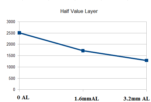
Graphic representation of the radiation field intensity being reduced by 1/2 as more Aluminum filters are added into the beam.
Beam Quality (Half Value Layer) measures the X-ray beam thickness, depth, and penetration. Half value layer is the ability of the material at which the intensity of radiation entering the material is reduced by 1/2 [or 50%]. Each x-ray device has its own HVL limit posted on the FDA website.
Test Frequency
Annually
SID
40”
Technique Factors
90kVp, 120 mA, 1000msec, filtration (0, 1.6mm Al, and 3.2mm Al)
Test Tools
A x-ray Quality Assurance meter (e.g. RTIs Piranha or Barracuda) and a HVL stand
Procedures
1. Place a QA meter on top of table with the HVL stand.
2. Set the SID to 40” and lock in place.
3. Take a series of eight shots without 0, 1.6 mm, and 3.2 mm Aluminum filtration at 90kVp, 120mA, and 1000 msec (1 second) settings.
4. Measure each exposure in milli-Roentgen (mR) and record.
5. Calculate the logarithmic value using this formula: ((1.6*LOG((2*F71)/B71))-((3.2*LOG((2*D71)/B71))))/LOG(F71/D71)
6. If HVL exceeds the maximum value, 3.2 mm Al at 90 KvP then additional filtration is required.
SID Detent / Scale Accuracy
SID Detent / Scale Accuracy is a qualitative measurement inspection of the SID detent operation and rotational scale. Technicians use a standard measuring tape and/or magnetic angle measuring tool to verify proper detent (40" - table and 72" - chest) and rotational angle (89 degrees and stop) operation.
Test Frequency
Annually
Test Tools
A tape measure tool.
Procedures
1. Set the SID to 40” and lock in place.
2. Verify 40" SID measurement using a tape measure from the collimator to cassette.
3. Verify 72" SID measurement using a tape measure from the collimator to cassette.
4. Verify measurements for 40" SID at the x-ray table and 72" SID at the chest stand and record.
5). Rotate the table vertically to 89 degree and using a magnetic angle measuring tool verify that the table scale reads 89 degrees. Additionally, rotate and check 90 degree collimator rotational scale for accuracy. As a rule of thumb, the SID detent and scale accuracy should be +/- 2%)
Illumination
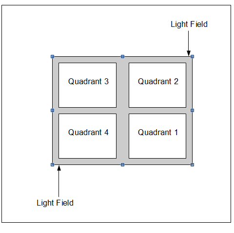
illuminance test of the four different quadrants.
The illuminance test measures the light field. This test is suppose to provide moer than enough light to define the x-ray field and the light shown under ambient (normal low lighting ) conditions.
Test Frequency
Annually
SID
40”
Test Tools
A Digital Light Meter
Procedures
1. Place a light meter on top of table.
2. Set the SID to 40” and lock in place.
3. Take a series of four light measurements at the four quadrants.
4. Measure each quadrant in foot candles (FC) and record.
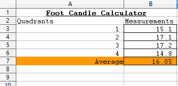

Foot candle calculator using .xls to calculate average
5. Take the average and if the average is greater than 15 FC then the light field illumination meets system requirements. As a rule of thumb, the allowable tolerance a minimum of 15 FC which means the average value must be greater than 15 FC.
Light Field Offset
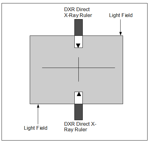
Fluke Biomedical DXR Direct X-Ray Ruler with arrows aligned into the light field.
Primary Method
The Light Field offset (Beam Size) is the distance that the light field is out of calibration to the radiation field. The light field is supposed to represent the surface area when it is to be irradiated by the x-ray beam. Ideally, the front surface area of the light field to the DXR Direct X-Ray Ruler should align near zero on the DXR ruler scale.
Realistically how the light field is projected, the light field offset can be affected by the position or adjustment of the light bulb, the type of light bulb, the position and/or angle of the mirror. In the US, the x-ray and light field alignment needs to be within 2% (.8 cm for a 40") of the SID .
Test Frequency
Annually
SID
40”
Technique Factors
70 kVp, 10 mA, 1000msec
Test Tools
A DXR Direct X-Ray Ruler
Procedures
1. Place the DXR Direct X-Ray Ruler into the light field.
2. Expose the DXR Direct X-Ray Ruler.
3. Examine each exposed DXR Direct X-Ray Ruler. Segments should turn on when the RaySafe DXR+ is irradiated.
4. Read any X-ray/light field deviation in the RaySafe DXR+ display and calculate the difference between the Length(s) (L1 + L2).
5. Read any X-ray/light field deviation in the RaySafe DXR+ display and calculate the difference between the Width(s) (W1 + W2).
Light Field / X-ray Field Alignment

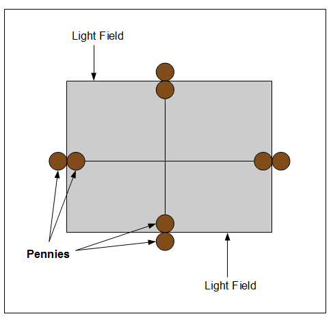
Eight penny (alignment) test
Alternate Method
The Light Field to X-ray Field Alignment (alternate test for Field Size Versus Indicators / Light Field Offset--Beam Size) is a two part test:
- x-ray / light field congruence (how far off center the radiation field is to the center of the light field) and
- x-ray / light field size (does the x-ray beam align with the field light? Are they exactly the the same size? same shape?).
The light field represents the surface area to be irradiated by the x-ray beam. Ideally, the center of the light field and x-ray field should match or be aligned. Realistically of how the light field is projected, the light field can be affected by the position or adjustment of the light bulb, the type of light bulb and the position or angle of the mirror. In the US, the x-ray and light field alignment needs to be within 2% (.8 cm for a 40") of the SID.
The second part of the test, checks the size of the light field which should be as close as the same size of the radiation field produced. If you set the collimator light to produce a 18 x 24 cm (8 x 10") and 24 x 30 cm (10 x 12") light field, the radiation field produced should be 18 x 24 cm (8 x 10") and 24 x 30 cm (10 x 12") after the cassette has been processed. In the US, the difference between the length/width of the light field and the radiation field needs to be less than 2% SID, and the sum of the length and width differences needs to be less than 4% (1.6 cm for a 40") of the SID.
Test Frequency
Annually
SID
40”--Table
72"--Chest Stand
Technique Factors
90 kVp, 10 mA
Test Tools
An 10”x12” cassette and 8 pennies
Procedures
1. Place a 24 x 30 cm (10 x 12") film cassette on the table.
2. Set collimator to 40” SID
3. Collimate light field to a 18 x 24 cm (8 x 10") size.
4. Mark the four sides of the light field. One method is to place two pennies together with medical tape so that the two pennies touch. Place the center of the two pennies on the edge of the light field. Do this on each of the four sides. Facing the film, place a penny or marker in the light field to identify the lower right corner of the film.
5. Expose and develop (process) the film.

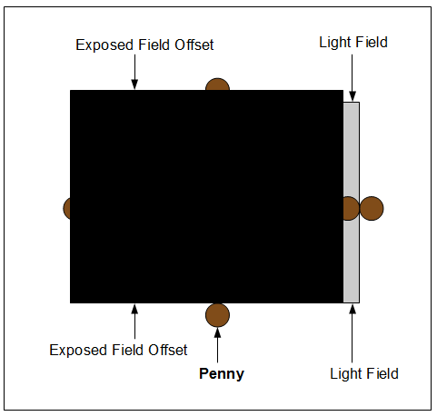
Examine each of the four sides of the film. All pennies should be shown and not fully covered
6. Examine each of the four sides of the exposed film. The inside pennies closest to the center of the light field shall lie partially or completely in the radiation light field. The outside pennies may partially lie in the exposed field but no outside penny can be fully covered by the radiation field or exposed field offset.
7. Misalignment in either dimension (horizontal misalignment is the sum of the deviation of the right and left edges, while vertical misalignment is the sum of the top and bottom edges) cannot exceed 0.8 inches. The deviations should be less than +/- 1/2 the diameter of the penny at any edge and must be less than +/- the diameter of the penny. In other words, the outside pennies should never be covered by the exposed field offset otherwise contact your OEM service engineer.
X-ray Field/Image Receptor Alignment
Primary Method
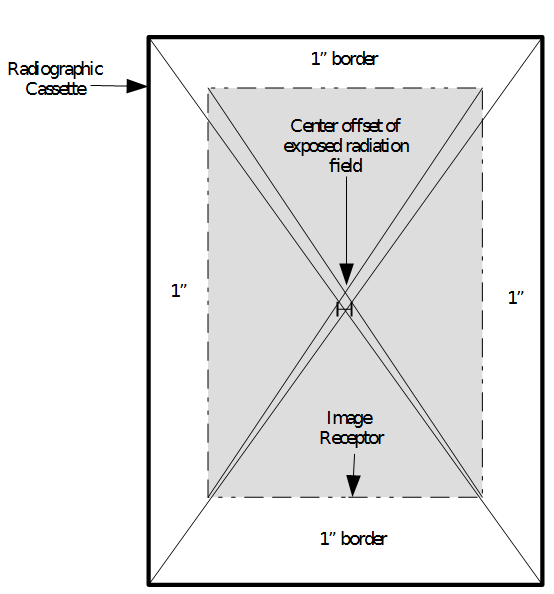
The Light Field to X-ray Field Alignment (Field Size Versus Receptor Offset) is the alignment of the center of light field to the center mark of the radiation beam. An image receptor or receptor is defined as the radiographic film cassette. This test defines where the light field is and verifies where the center radiation field exposure is to prevent image alignment distortion. In the plane of the image receptor , the misalignment, of the edges is visually defined by the center light field with the edges to the exposed center x-ray field. The misalignment must not exceed 2% of the focal spot to image receptor distance.
Test Frequency
Annually
SID
40”--Table
72"--Chest Stand
Technique Factors
90 kVp, 10 mA
Test Tools
An 10”x 12” cassette and a ruler (in inches)
Procedures
Using a ruler the center of the field light to the center of the exposed film should be less than 2% (or .8cm) at 40" SID. If greater than .8cm then possible adjustment of the collimator light is warranted
1. Place a 18 x 24 cm (8 x 10") cassette in table bucky.
2. Set collimator to 40” SID.
4. Manually collimate the light field around the rectangular frame of the cassette. (You should collimate so that the light field leaves a 1" unexposed border on the film after the film has been processed.)
5. Expose and process the film.
6. To find the center of the film, place a ruler at opposite corners of the 18 x 24 cm (8 x 10") film and draw a line. The point where the two lines cross is the center of the film. Because film has rounded edges, some estimating will have to be done when positioning the ruler in opposite corners.
To find the center of the exposed portion of the film, place the ruler at opposite corners of the exposed portion of the film and draw a line. The point where the two lines cross is the center of the exposed radiation field.
7. To find the center of the exposed portion of the film, place the ruler at opposite corners of the exposed portion of the film and draw a line. The point where the two lines cross is the center of the exposed radiation field.
8. Measure the distance between the center point of the film and the center point of the exposed radiation field.
9. Record this information. As a rule of thumb, the center of the field light to the center of the exposed film should be less than 2% (.8cm at 40") SID.
Field Sizing (PBL)

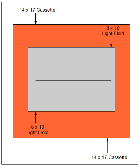
An 18 x 24 cm (8 x 10") cassette in bucky auto-collimates light field to the 18 x 24 cm (8 x 10") size.
The Field Sizing Positive Beam Limitation (PBL) tests how the collimator automatically adjusts to an exact cassette size after a cassette is placed inside the bucky. The x-ray beam shall not differ from the image receptor size by more than 3% of the SID in any one dimension or a total of 4% of the SID in both dimensions.
Test Frequency
Annually
SID
40”--Table
72"--Chest Stand
Technique Factors
90 kVp, 10 mA
Test Tools
An 18 x 24 cm (8 x 10") cassette, a 35 x 43 cm (14" x 17") cassette, and a ruler (in inches)
Procedures

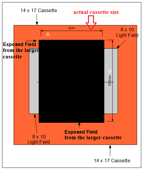
A. Actual film 8" cassette size. B. Actual film 10" cassette size.
1. Place an empty, 18 x 24 cm (8 x 10") cassette inside the bucky.
2. Check that the collimator is in the automatic mode.
3. Set the SID to 40” and lock in place.
4. Place a loaded, 35 x 43 cm (14" x 17") cassette on top of the table.
5. Rotate the x-ray tube to 90 degrees so the x-ray tube is perpendicular to the large cassette.
6. Activate the light field.
7. Make an exposure and process the film from the 35 x 43 cm (14" x 17") cassette from on top the table.
8. If the exposed field size from the 35 x 43 cm (14" x 17") cassette does not exceed the actual 18 x 24 cm (8 x 10") film size, then the PBL meets system requirements. On the other hand, if the exposed field size from the 35 x 43 cm (14" x 17") cassette exceeds the actual 18 x 24 cm (8 x 10") film size for the cassette, then triangulation calibration must be performed to determine the actual 18 x 24 cm (8 x 10") field size.
9. Measure the exposed field "Width" from left to right and record 8" (35 cm).
10. Measure the exposed field "Length" at near from top to bottom and record 10" (24 cm).
11. Record this information. As a rule of thumb, the allowable tolerance at 40" SID is less than 1.6 cm and at 72" SID is less than 2.8 cm (or 4%)
Tube Current Output
(WARNING: LETHAL VOLTAGES PRESENT)
The Tube Current is MilliAmperage Seconds (mAs). This verification test measures invasively the electronic x-ray timing circuit and mAs circuit to assure that the exposure time and mAs set on the radiographic equipment display is accurate and precise.
Test Frequency
Semi-Annually
SID
40”
Technique Factors
- mA: 25 mAs, 40 mAs, 80 mAs, 160 mAs, 320 mAs, and 640 mAs
- kVp: 60 kVp, 80 kVp, and 120 kVp
- Time: .5 seconds
Test Tools
A mAs meter
Procedures
1. Remove the high voltage generator cover and locate the mA test points.
2. Set the SID to 40” and lock in place.
3. Take a series of six shots without any filtration at 20 mA, 40 mA, 80 mA, 160 mA, 320 mA, and 640 mA settings. Additionally, these six series of shots will be performed at a time setting of .5 as well as 60 kVp, 80 kVp, and 120 kVp, stationary kVp settings.
4. A 50 mA setting multiplied by .50 timer equals 25 mAs (50mA x .5sec = 25mA). On the mAs meter you should read 25 mAs. Additionally, do not forget to reset the mAs meter during every shot.
5. Measure each exposure in mA and record. As a rule of thumb, the allowable tolerance at 40" SID is +/- 10%
Linearity
Linearity is the ability of an x-ray unit to produce a constant, steady radiation output, at a given mA, using various combinations of mAs and time.nowing that the measured x-ray dose (mR/mAs) being delivered is stable or linear is a comfort to the physcisit and to the patient to ensure no devitaions of measurments are being recorded in realtime. If the measurments are changing over time, the likelyhood of patient over exposure to radiation will result. Recording linearity is a risk prevention and management technique that is an FDA mandate to measure and record.
Test Frequency
Semi-Annually
SID
40”
Technique Factors
- mA: 50 mA, 100 mA, 160 mA, 320 mA, and 640 mA
- kVp: 60 kVp, 80 kVp, and 120 kVp
- Time: .5 seconds
Test Tools
A X-ray Quality Assurance meter (e.g. RTIs Piranha or Barracuda)
Procedures
1. Place a QA meter on top of table.
2. Set the SID to 40” and lock in place.
3. Take a series of six shots without any filtration at 50 mA, 100 mA, 160 mA, 320 mA, and 640 mA settings. Additionally, these six series of shots will be performed at 60 kVp, 80 kVp, and 120 kVp, stationary kVp settings.
4. Measure each exposure in mR and record.
5. Perform mR/mAs calculations. The constant, steady output is measured in mR. Note: mR/mAs is divided by its corresponding mAs and mR measurement to equal mR/mAs. Next, the mR/mAs AVERAGE is the average measurement of all the mR/mAs results. Finally, we calcuate a 10% tolerance by multiplying the mR/mAs AVERAGE by .9 (low range) and 1.1 (high range).
Entrance Skin Exposure
Entrance Skin Exposure (ESE) is the measurement of radiation dosage at the entry point of a patients skin for the most common X-ray examinations, to include fluoroscopic and conventional radiology techniques. Traditionally, we compare the facility’s entrance skin exposure for chest, abdomen and LS spine examinations to that obtained during the Annual Medical Physicist’s Radiographic QC Survey. These units are measured in milli Roentgen (mR).
Test Frequency
Semi-Annually
SID
40”
Technique Factors
32 mA, no filtration (Air Kerma)
Test Tools
A X-ray Quality Assurance meter (e.g. RTIs Piranha or Barracuda)
Procedures
1. Place a QA meter on top of table.
2. Set the SID to 40” and lock in place.
3. Take a series of four shots without any filtration at 60 kVp, 80 kVp, 100 kVp, and 120 kVp while the 32 mAs always stays the same.
4. Measure each kVp exposure in milliRoentgen (mR) and record.
Kilovoltage Verification
The Kilovoltage Verification (KvP) measures noninvasive the electronic x-ray tube voltage test to assure that the tube voltage set on the radiographic equipment display is correct.
Test Frequency
Semi-Annually
SID
40”
Technique Factors
- mA: 50 mA, 100 mA, 125 mA, 160 mA, 320 mA, and 640 mA
- kVp: 60 kVp, 80 kVp, and 120 kVp
- Time: .5 seconds
Test Tools
A X-ray Quality Assurance meter (e.g. RTIs Piranha or Barracuda)
Procedures
1. Place a QA meter on top of table.
2. Set the SID to 40” and lock in place.
3. Take a series of 6 shots with no filtration at 50 mA, 100 mA, 125 mA, 160 mA, 320 mA, and 640 mA settings. Verify 60kVp, 80kVp, and 120kVp measurements are constant at varying mA shots (space charge).
4. Measure each exposure in kVp and record. As a rule of thumb, the allowable mA tolerance is +/- 5% and kVp +/- 4.
MilliAmperage Verification
(WARNING: LETHAL VOLTAGES PRESENT)
The MilliAmperage (mAs) Verification measures invasive the electronic x-ray mAs test to assure that the tube amperage in mA set on the radiographic equipment display is correct.
Test Frequency
Semi-Annually
SID
40”
Technique Factors
- mA: 50 mA, 100 mA, 125mA, 160 mA, 320 mA, and 640 mA
- kVp: 60 kVp, 80 kVp, and 120 kVp
- Time: .5 seconds
Test Tools
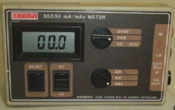

A Keithley mA/mAs meter
A mAs meter
Procedures
1. Remove the high voltage generator cover and locate the mA test points.
2. Set the SID to 40” and lock in place.
3. Take a series of 6 shots with no filtration at 50 mA, 100 mA, 125mA, 160 mA, 320 mA, and 640 mA settings. Verify these 6 series of mA shots are within tolerance.
4. Measure each exposure in mA and record. As a rule of thumb, the allowable mA tolerance is +/- 5% and kVp +/- 4.
Action Required
Action Required is where the inspector can record any notes.
Form
- DD 2164 - X-RAY VERIFICATION/CERTIFICATION WORKSHEET
- AF Form 2025 - POST-CALIBRATION RADIATION INSPECTION RECORD RADIOGRAPHIC (11 July 1982)
References
Links
- Guide for Radiation Safety/Quality Assurance Programs
- COMPUTED RADIOGRAPHY (CR)/DIGITAL RADIOGRAPHY (DR) STATE X-RAY INSPECTION PROTOCOL
- CFR-Code of Federal Regulations Title 21: Sub-chapter J: Radiological Health Part 1020
- Safety Code 35 Summary Quality Control Procedures Radiography/CR/DR
- Resource Manual for Compliance Test Parameters of Diagnostic X-Ray Systems
- Basic Physics of Digital Radiography